
= Setting the standard mode selection parameter will be referred to in this manual as performing a TYPE X RESET, where X is the parameter setting value.Additionally, this version number can be read from inverter memory by displaying the parameter CPU VERSION in GROUP:UTILITY PARAMETERS. The main software version number is printed on the CPU package (IC1) on the control board. An error will occur if the option ROM is installed in an inverter with pre-V120 main software. Interface Board Installation / Removal The Profibus Communications Option ROM enclosed with the Profibus kit is compatible only with G3 inverters with V120 or later main software. Interface Board Diagram Standoff mounting holes Plated SHIELD connection point for grounding (refer to Section 3).Ģ. 49 11.2.11 GROUP:AM/FM TERMINAL ADJUSTMENT PARAMS.50 11.2.12 GROUP:UTILITY PARAMETERS.51 11.2.13 GROUP:MOTOR RATING PARAMETERS. ġ1.2.7 GROUP:PROTECTION FUNCTION PARAMETERS.43 11.2.8 GROUP:PATTERN RUN CONTROL PARAMETERS.45 11.2.9 GROUP:FEEDBACK CONTROL PARAMETERS.48 11.2.10 GROUP:COMMUNICATION SETTING PARAMETERS. 6 2.2 Installation Procedure.7 2.3 Removal.

Avoid installation locations that may be subjected to rapid changes in temperature or humidity.
#Toshiba g3 tosvert 130 software programs series
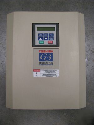
HIGH PERFORMANCE TRANSISTOR INVERTER TRUE TORQUE CONTROL DRIVE SERIES PROFIBUS-DP COMMUNICATIONS INTERFACE December, 1998 ICC #10160-001


 0 kommentar(er)
